Product Overview
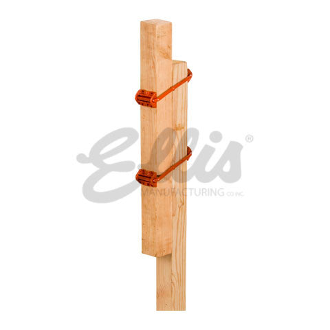
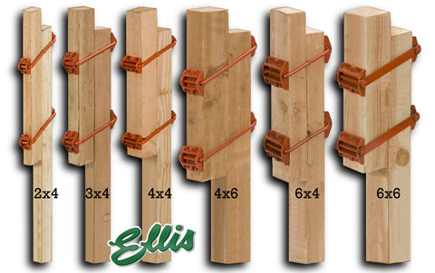
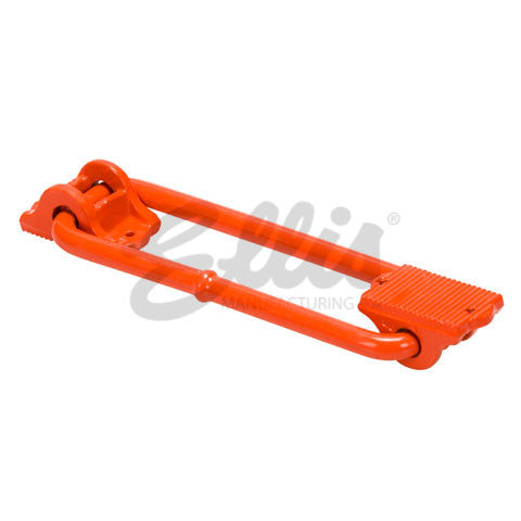
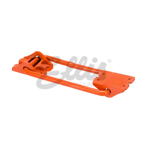
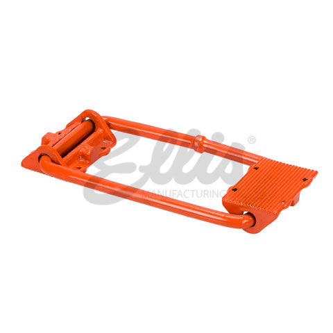
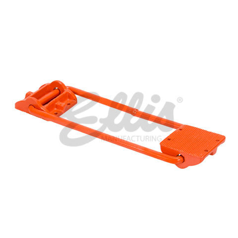
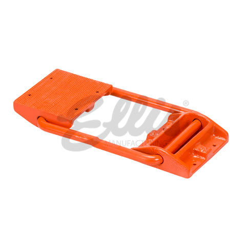
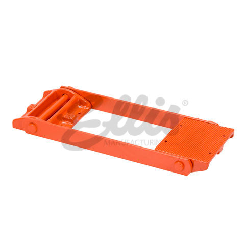
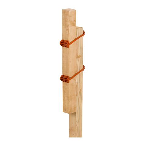
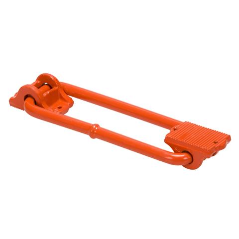
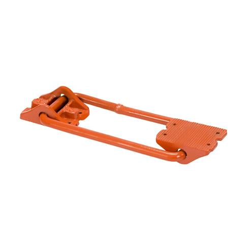
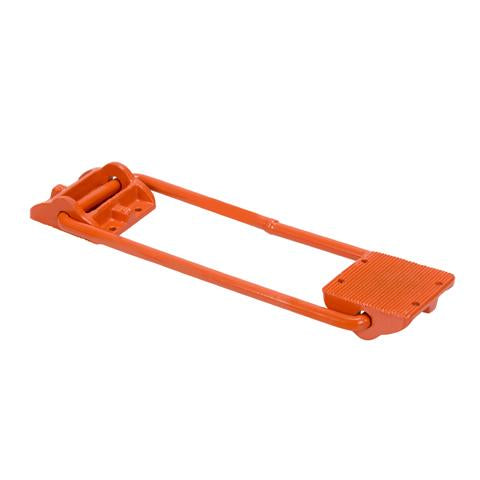
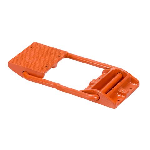
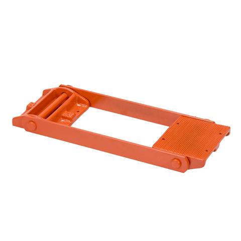
The secret of the Ellis Shore is the Ellis Clamp. Patented by Ellis Manufacturing Company Inc. in the 1950's, the Ellis Clamp is simply designed to bring two pieces of lumber together to quickly and easily create an adjustable shore. By using Ellis Shoring Methods, concrete contractors are able to extremely reduce the amount of time and resources spent on building their post shores. The Ellis clamp is designed with a solid steel rectangular collar and two heavy duty malleable castings, which are grooved on the flat surface for firm gripping on lumber. Abuse will not break or distort, making the clamp durable enough to use hundreds of times and its cost per use 'pennies'. The Ellis Clamp is available in eight sizes to fit most nominal lumber sizes as shown in the load chart below.
Demonstration Video
Specifications
S.E.A.S
SAFETY! Dating as far back as the late 1940's, the Ellis Shoring System has a proven track record of safety and reliability. Ellis shoring methods assure a 2.5 : 1 safety factor. Shores are double-strong in the middle to prevent buckling; for adequate bracing, nail at any point.
ECONOMY! Low initial cost, hundreds of reuses, great time savings, less waste.
ADAPTABILITY: Use the same Ellis Shores on different types of concrete shoring jobs in quick succession. Ellis Shores are perfect for shoring many types of concrete jobs - suspended floor slabs, columns, beams, overpasses, dams, culverts, ramps, bridges, residential, commercial and industrial.
SPEED! Ellis 'Up & Down' Faster Method is a job-proven speed advantage. Fewer skilled men required... Ellis Shores simply slip into place - a big time saver for your next concrete shoring job.
Materials:
Lower Shore Members are composed of two Ellis Clamps with pivotal castings, permanently attached with threaded nails 2" from the top, 12” apart, c to c; upper shore member of sufficient length to obtain desired height; both lower and upper members of No. 1 Douglas Fir or Yellow Pine, free of heart center and ends squared.
Length:
For jobs requiring shores 20’ or less the lower shore member should be 6' or 7’ and the upper shore member long enough to reach desired height. For shores over 20’, we suggest putting the upper (or longer) member at the bottom and the lower shore member (with two clamps attached) at the top. By doing this, the bottom member can be braced at recommended intervals and adjustments can be made to the top member by workmen working off scaffold planks laid across the bracing. This eliminates removing several rows of bracing to make minor adjustments.
Info & Guides
- How to use Ellis Shores
- Ellis Shore load chart with lacing and bracing
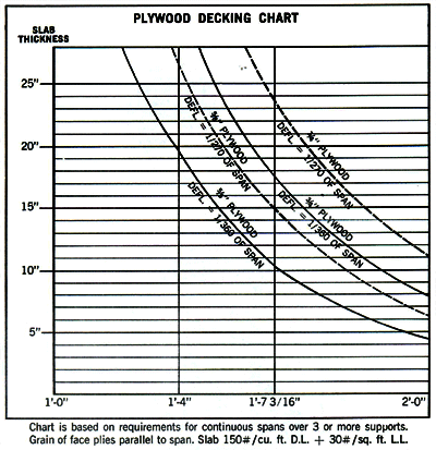
- Ellis 4x4 Shore spacing chart for various slab thickness
- How to Build the Ellis Shoring System
- Lacing Guide
Safe Working Loads
| Total Shore Height (Ft.) |
Lower Shore Member Length |
Clamp Spacing |
Ellis Shore Maximum Safe Working Load (lbs.)
Testing based on use of 2 shore clamps and #1 Doug fir or #1 SYP nominal lumber. |
|||||
|
2x4
|
3x4
|
4x4
|
4x6
|
6x4
|
6x6
|
|||
| 18' | 7' | 18" | 0 | 0 | 0 | 3200 | 3200 | 7200 |
| 16' | 7' | 18" | 0 | 0 | 0 | 3200 | 5600 | 10,400 |
| 14' | 7' | 18" | 0 | 0 | 3000 | 4000 | 7200 | 13,600 |
| 12' | 6' | 12" | 600 | 2000 | 4400 | 6000 | 9600 | 13,600 |
| 10' | 6' | 12" | 1000 | 3000 | 6000 | 8000 | 12,000 | 16,000 |
| 8' | 6' | 12" | 1500 | 4000 | 6000 | 9600 | 16,000 | 16,000 |
| 6' | 4' | 12" | 1800 | 5000 | 6000 | 9600 | 16,000 | 16,000 |
The above chart is based on ACTUAL load tests and includes a 2-1/2 to 1 safety factor. Data not for construction without approval from a certified structural engineer.
Using Ellis Shores to reshore? Try the Ellis Reshore Spacing Calculator.

