Product Overview
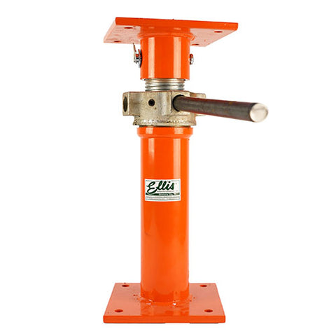
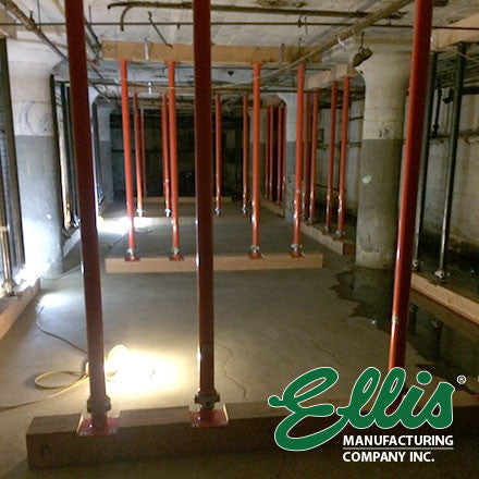
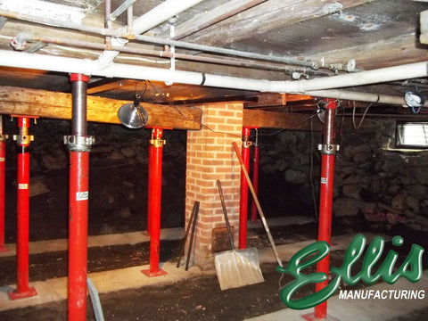
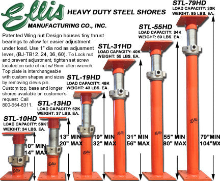
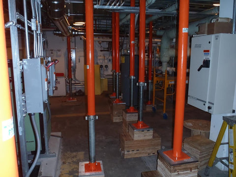
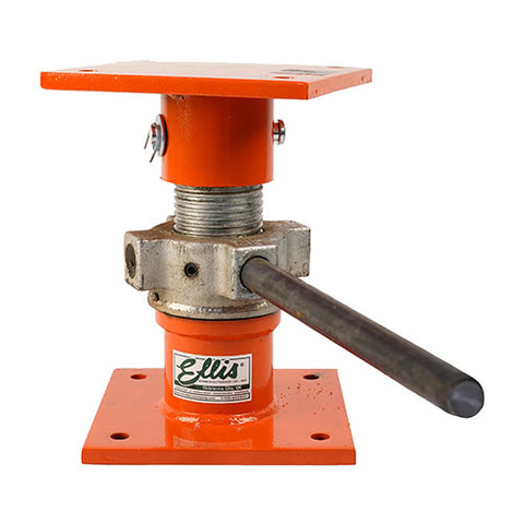
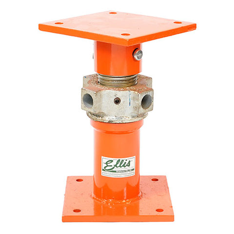
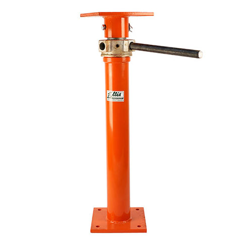
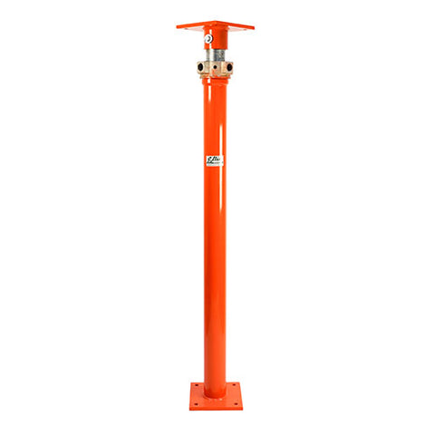
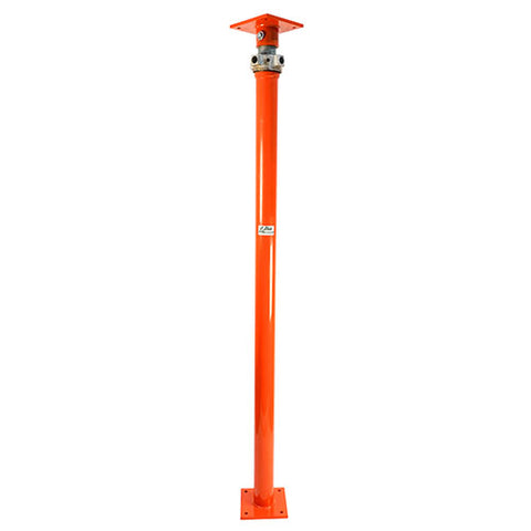
Ellis Heavy Duty Steel Lifting Shores are for temporary or permanent shoring applications. Use the Ellis Heavy Duty Shore to support up to 56,000 lbs. To use measure shoring height, select the appropriate Ellis Heavy Duty Steel Shore, set shore in place, use 1" Steel Adjustment Rods to adjust height (NOT INCLUDED). Once shore is in place and adjusted to desired height simply tighten set screw (on side of nut) to lock nut to set shore for permanent support solution. These shores are also know as jack posts.
Demonstration Video
Specifications
Top Plate - 8"x8"x1/2", 4 - Holes 9/16" Dia., spaced 1" OC from edges. Tops are Interchangeable with Custom Sizes upon request.
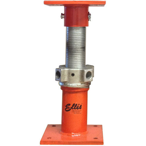
Acme Screw - 2.875" Dia., Approx. 4 Acme Threads per inch, Galvanized, Length varies.
Adjustment Nut - Forged and Galvanized for durability, 6" Wide. 4 - 1.063" Dia. Holes as leverage points to make adjustment with 1" Dia. Turning Rod (Item #'s BJTB-12, BJTB-24, BJTB-36, BJTB-60).
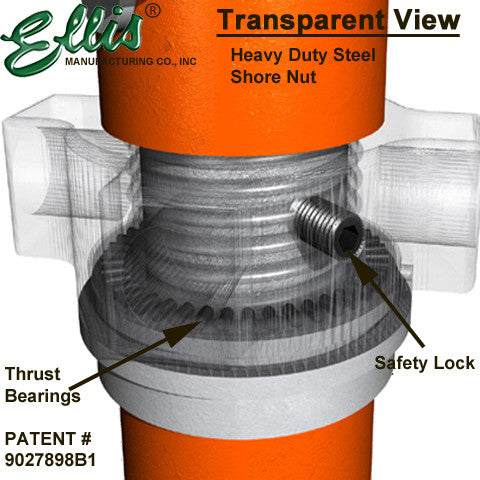
Thrust Bearings & Safety Lock - This patented design, found in Light and Heavy Duty Steel Shores, greatly reduces the amount of friction caused when adjustment to the nut is made when the shore is under load and significantly increases its jacking capability. Unlike the standard steel shore, thrust bearing shores are built as one complete unit to aid in uplift resistance and do not come apart. We have also added the Safety Lock set screw in the side of the nut. When tightened down, the adjustment nut locks in place for permanent or long term shoring applications.
3" Sch. 40 Pipe - 3.5" OD, 3.068" ID, Length varies.
Base Plate - 8"x8"x1/2", 4 - Holes 9/16" Dia. spaced 1" OC from edges. (Custom base available upon request)
*Load capacity includes a 2.5 to 1 factor of safety.
*Do not lift more than 20,000 lbs.
*Steel Shores should be attached to a flat solid foundation and should not be subject to any lateral force. Heavy Duty Steel Shores should be used to support straight vertical loads only. We recommend tightening set screw in the side of the 4 hole nut with 6mm allen wrench prior to loading (unless lifting). Do not extend screw past advertised adjustment range. Before construction begins it is recommended that you consult with certified engineer for approval of our products within your application.
Documents:
Shop Drawings and CAD Blocks:
| Item Number | Shop Drawing (.PDF) | AutoCAD Block (.DWG) |
| STL-10HD | STL-10HD Shop Drawing | STL-10HD CAD Block |
| STL-13HD | STL-13HD Shop Drawing | STL-13HD CAD Block |
| STL-19HD | STL-19HD Shop Drawing | STL-19HD CAD Block |
| STL-31HD | STL-31HD Shop Drawing | STL-31HD CAD Block |
| STL-55HD | STL-55HD Shop Drawing | STL-55HD CAD Block |
| STL-79HD | STL-79HD Shop Drawing | STL-79HD CAD Block |
| STL-103HD | STL-103HD Shop Drawing | STL-103HD CAD Block |
| STL-127HD | STL-127HD Shop Drawing | STL-127HD CAD Block |
| STL-151HD | STL-151HD Shop Drawing | STL-151HD CAD Block |

